Technical Support
Photocell to bypass ACM-1 during daylight
The ACM-1 AC Current Monitor can be used with the RFC-1/B to detect and measure AC current draw in external devices such as tower lighting systems. When properly programmed, the RFC-1/B can contact appropriate personnel when an over or under current condition exists.
!Automatic monitoring does not relieve you of any FAA or FCC obligations regarding tower light monitoring.
Tower obstruction lighting must be checked daily for proper operation. Because of the potentially serious consequences of obstruction lighting failure on a tower, many stations want to have an automatic means to continuously monitor the obstruction lighting and to be notified immediately of a failure.
Alarm Block
Since tower lighting is not normally used during daylight hours, it may be useful to ignore the status of tower lights during daylight. One way to do this with the RFC-1/B is to "block" the tower light alarm during daylight hours.
The problem with blocking alarms is that normal daylight hours fluctuate with the seasons. This makes it difficult to program the alarm block so that daylight hours are always blocked and nighttime hours are not blocked.
Photocell
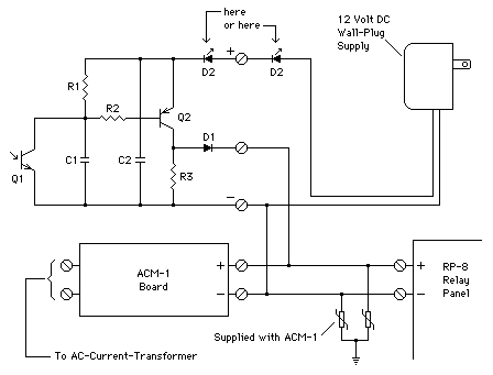
A more accurate method of inhibiting tower lighting alarms during daylight is to bypass the ACM-1 telemetry sample during daylight using a photosensor. The circuit below does this and costs only a few dollars to build.
The idea behind this circuit is to insert a DC voltage at the RP-8 telemetry input terminals during daylight that prevents the telemetry alarm from occurring. Simply put, the RFC-1/B thinks the lights are on. At night, the "fake" sample voltage is removed and the signal from the ACM-1 is monitored.

Photocell Bypass Schematic
| Qty | Description | Location |
|---|---|---|
| 1 | Photo transistor | Q1 |
| 1 | PNP transistor, 2N2907A or MPS2907 | Q2 |
| 1 | diode, 1N4005 | D1 |
| 1 | LED (optional–lights during daylight) | D2 |
| 2 | 0.1 µF monolithic ceramic capacitor | C1,C2 |
| 1 | 33K Ohms resistor, 1/4W, 5% | R1 |
| 1 | 10K Ohms resistor, 1/4W, 5% | R2 |
| 1 | 1K Ohms resistor, 1/4W, 5% | R3 |
| 1 | Power supply, 12 VDC, 500 mA | T1 |
The circuit can be built on a small piece of pre-punched PC board. The light sensor (Q1) should be pointed toward the southern sky. A light shield can be placed around the sensor if necessary. A short length of heat-shrinkable tubing works well.
If nothing more elegant is available to weatherproof the circuit, an inverted glass baby food jar can be used with a dab of RTV (silicon seal) to seal the hole in the lid where the cable passes through it. A foil-shielded cable such as Belden 8451 is recommended.
The sensitivity of the photosensor is controlled by R1. Lower values decrease the sensitivity, 33K is typical and do not make R1 lower than 1.5K. The LED (D2) should indicate daylight at least up until the time the tower lights turn on.
Unlike the ACM-2, the ACM-1 does not have an input to attach this circuit. It must be connected as shown in the schematic. Connectors may be added to the circuit to ease installation.
Once the photosensor is installed, the telemetry for the tower lights will read normally at night, usually 100.0%, and will typically read a much higher value during the day–usually full-scale. The full-scale reading depends on how the telemetry channel is programmed.
Take that into consideration when programming an alarm for this input. Set the upper limit to 9999 and the lower limit to the appropriate alarm point. This way the upper limit is ineffective and the lower limit sets the active trip point.
