Frequently Asked Questions
LED Indicators Inoperable
There is a connector inside the RFC-1/RAK that can become loose in shipping. When this happens, the control signals between the RFC-1/B and the the RAK-1 are interrupted and the front panel LED indicators are inoperable. Data communications may also be affected.
The system is not damaged if it operates without the jumper cable in place.
The most obvious symptom of this is that the data mode LED is always on even when the system is operating in voice mode. RFC-1/RAK systems are set to operate in voice mode from the factory. It is normal for the RFC-1/RAK to switch briefly to data mode at power up when the system initializes the hardware.
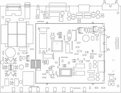
Jumper cable location inside RAK-1
The front panel indicators of the RAK-1 are driven by signals from an embedded RFC-1/B board. The connection between the two boards is made by a very short jumper cable that is terminated with two DIP jumpers. The connector does not have a latching mechanism and may vibrate loose in transit.
Reinstalling the Jumper Cable
Verify that the jumper cable connectors are seated properly in their sockets. The drawing above shows the location of the connector (shaded) when it is installed correctly.
- Remove the two philips screws from the top cover on the rear of the RAK-1 chassis and slide off the top cover.
- Align each connector with the notched edge of the corresponding socket and press carefully into place.
- Replace the top cover using the two screws that were removed in step 1.
The jumper cable consists of a pair of 16-pin DIP style connectors joined by a very short length of flat cable. The connectors are usually black and the cable is gray. Newer RFC-1/B revisions have a 20-pin socket so they will have four empty positions–this is normal.
Make sure that none of the pins are bent and that all of the pins line up over their corresponding position in the sockets. It should not require much force to install correctly.