Frequently Asked Questions
Telephone Line Hum or Line Seizure
Unexpected line seizure is most often caused by a simple programming mistake. Verify the programming of the hardware version before assuming that hardware has failed. See the Links section to the right of this page.
A limited number of RAK-1 systems have a problem that potentially connects the telephone line to chassis. The RAK-1 systems in question have board revision 5–the revision number is printed on the top layer of the RAK-1 board near the the battery connection wires.
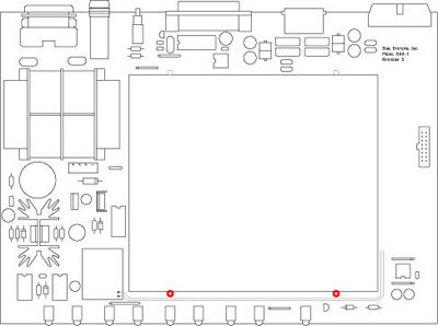
RAK-1 version 5 potential chassis issue
A telephone line signal passes very close to two board standoffs on the underside of the board. The potential points of contact are shown in red in the drawing above. This condition exists only on board revision 5. The issue was resolved on version 5A.
Resolution
If you determine that you have RAK-1 revision 5 and are experiencing intermittent telephone line hum and/or line seizure, there is an easy solution that requires:
- a small philips type screwdriver
- a small flat blade screwdriver
- 2 nylon washers or similar non-conductive material
When the systems were assembled the protective coating on the surface of the PC board protected this trace from shorting against the metal standoffs. However, with pressure from the mounting screw and vibration in transit and/or rack mounting, the surface coating may wear through and expose this trace to the chassis.
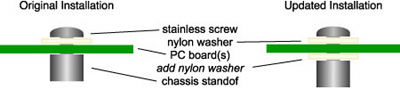
RAK-1 insulating washer installation
The solution is to insulate the two potential points of contact from the chassis by inserting a thin nylon washer in between the standoff and the board.
Observe normal precautions for handling static sensitive devices while performing this procedure.
Procedure
- Disconnect all cables from the RAK-1 and remove it from the equipment rack.
- Remove the top cover by releasing the 2 philips screws from the rear edge and sliding the top cover out of its mounting rails.
- Looking down into the RAK-1 there are 4 philips screws holding the RFC-1/B board in place with 4 nylon washers, remove them.
- Use a small flat blade screwdriver to remove the short DIP connector jumper cable that connects the RFC-1/B (J4) to the RAK-1 (J9)–try not to bend the pins.
- Disconnect the flat cable connector that connects the RFC-1/B (J3) to the RAK-1 (J6).
- Disconnect the 2 modular phone jumpers that connect the RFC-1 (J1 & J2).
- Remove the RFC-1/B board from the RAK-1 unit and carefully set it aside.
- Insert a thin washer made of nylon or other non-conductive material in between the PC board and the chassis mounting standoff at the two RFC-1/B mounting positions along the front side of the chassis–see images for mounting positions and detail of insertion point. There should be enough flex in the RAK-1 board to allow the washers to slide easily into place.
- Install the RFC-1 board back in the chassis–attach the connectors in reverse of the order they were removed: modular connectors, flat cable jumper, then DIP jumper.
- In some systems the RFC-1 expansion port (J4) is a 20 pin socket while the DIP jumper and RAK-1 socket have only 16 pins. Align the connector against the notched end of both sockets. There will be unused pins on J4 at the far end away from the notch as shown on this page.
- Install the RFC-1 mounting screws with nylon washers–do not over-tighten
- Slide the top cover back into place and install the 2 philips screws.
- A test call can be made to the system at this point by connecting only a phone line and power. It is not necessary to connect the relay panels for this test.
- Install the RFC-1/RAK system back in the equipment rack and attach all connectors removed in step 1.
If nylon washers are not available, nearly any thin insulator will work. A couple of layers of black electrical tape will do the job.